Conclusion
We hope that you enjoyed building your cloud connected blinky project.
Through this tutorial, you configured, built, flashed, and monitored your firmware using PlatformIO. Your device is registered as an AWS IoT thing in your AWS account, and uses secure cloud connectivity through on-board secure hardware. Finally, you connected to AWS IoT Core, sent messages from the device over MQTT, and received an MQTT message from the AWS IoT console’s MQTT client to toggle the device’s lights on and off.
While the Core2 for AWS program does not teach C programming or require it as a prerequisite, it is critical to understand for embedded development. The control and flexibility provided through low-level code lets you use your hardware to its maximum potential. If you want to dive into the application code we provide in this program and are curious to learn more about C programming, Jens Gustedt provides a free course called Modern C under the Creative Commons license. It’s an excellent course and free to download .
Let’s take a minute to look a little deeper into what you accomplished through this tutorial.
What’s happening on the device
The FreeRTOS kernel
The application on the device uses the FreeRTOS kernel (for more information, see What is an RTOS? ). It bundles into the binary (application code) that you compiled with other libraries and drivers. The FreeRTOS kernel operates as a scheduler, and organizes blocks of sequential code as a task to give each task a share of processor runtime. There are tasks that typically loop forever to create messages that are sent to AWS, process received messages, update the display, and blink the LEDs.
We are proud that the Core2 for AWS contains a 240MHz dual core processor. However, this pales in comparison to today’s computers that contain 4+GHz processors with 8+ cores. To make the most out of the precious processor resources in the device, the FreeRTOS kernel maintains tasks in a state , such as running or suspended. The FreeRTOS kernel gives microcontroller applications the ability to optimize the processor by rapidly switching between individual tasks. A task can run after another task is in a suspended or blocked state (see the following diagram).

- The MQTT task transitions to a running state to send or receive messages.
- The MQTT task transitions to a blocked state and the display task transitions to running.
- The display task is blocked and the MQTT task starts running.
- The MQTT task is blocked and the blink task starts running.
- The blink task is blocked and thedisplay task starts running.
- The display task is blocked and the blink task starts running.
- The blink task is blocked and the display task starts running.
The RTOS kernel gives the appearance of concurrency and greatly improves an embedded application’s performance when compared to a simpler super loop application .
While super loop applications are simpler to program, areas of code that block/delay running of other code cause the MCU to sit idle. A device connecting to the AWS cloud will have variable round-trip latency and bandwidth constraints that make the performance advantage of using an RTOS necessary. An RTOS provides significant advantages for other applications where it’s paramount to not lose data or perform a critical operation without being obstructed by another code block running (e.g., health and safety), or to simply drive a smooth display screen.
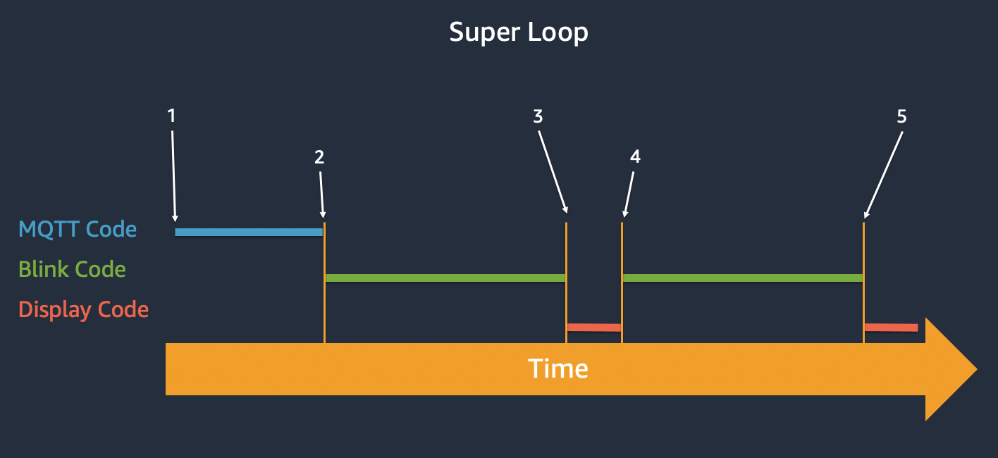
- The MQTT message interrupt starts to send and receive messages.
- The MQTT process finishes, and the blink code starts and turns on the LEDs. Code runtime pauses for 500ms, the LEDs toggle off, and code runtime pauses for 500ms.
- The blink code finishes and the display code starts.
- The display code finishes and the LEDS toggle on. Code runtime pauses for 500ms, the LEDs toggle off, and code runtime pauses for 500ms.
- The blink code finishes and the display code starts.
To learn more about RTOS and FreeRTOS, see the Introduction to RTOS video series and visit FreeRTOS.org .
AWS IoT Device SDK for Embedded C
The
AWS IoT Device SDK for Embedded C
used in this tutorial provided simplified connectivity and messaging to and from AWS IoT. It also worked with the included secure element library to make device authentication easy. To review and learn more, the Device SDK for Embedded C is located in the Core2-for-AWS-IoT-EduKit/Blink-Hello-World/components/esp-aws-iot/ folder; see
AWS IoT Device SDK for Embedded C
.
The board support package - device drivers
The device’s hardware features are bundled as a board support package (BSP). The BSP are drivers with APIs that provide a simplified way to access the hardware features. Feature examples include the screen, power management chip, secure element, speaker, microphone, 6-axis inertial measurement unit (IMU), touch driver, and LED bar.
On to Smart Thermostat .
Questions? Please use AWS re:Post
AWS IoT Kit now features direct access to
AWS re:Post
, which is a community-driven, questions-and-answers service. Search re:Post using the
AWS IoT Kit
tag to see if your question has been asked and answered. If not, ask a new question using the AWS IoT Kit tag.